You have been asked to evaluate an OSPF network setup in a test lab and to answer questions a customer has about its operation. The customer has disabled your access to the show running-config command.
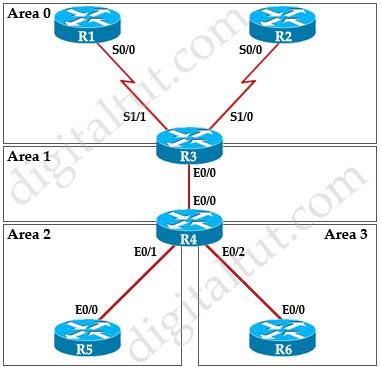
Although in this sim we are not allowed to use “show running-config” command but we post the configuration here so that you can understand more about the topology.
| R1 interface Loopback0 ip address 1.1.1.1 255.255.255.255 ! interface Serial0/0 ip address 192.168.13.1 255.255.255.0 ip ospf network non-broadcast ! router ospf 1 network 192.168.13.0 0.0.0.255 area 0 network 1.1.1.1 0.0.0.0 area 0 |
R2 interface Loopback 0 ip address 2.2.2.2 255.255.255.255 ! interface S0/0 ip address 192.168.23.2 255.255.255.0 ip ospf network non-broadcast ! router ospf 1 network 192.168.23.0 0.0.0.255 area 0 network 2.2.2.2 0.0.0.0 area 0 neighbor 192.168.23.3 |
R3 interface Loopback 0 ip address 3.3.3.3 255.255.255.255 ! interface Ethernet0/0 ip address 192.168.34.3 255.255.255.0 ! interface S1/0 ip address 192.168.23.3 255.255.255.0 ip ospf network non-broadcast ! interface S1/1 ip address 192.168.13.3 255.255.255.0 ip ospf network non-broadcast ! router ospf 1 network 192.168.13.0 0.0.0.255 area 0 network 192.168.23.0 0.0.0.255 area 0 network 192.168.34.0 0.0.0.255 area 1 network 3.3.3.3 0.0.0.0 area 0 area 1 virtual-link 4.4.4.4 neighbor 192.168.23.2 |
| R4 interface Loopback 0 ip address 4.4.4.4 255.255.255.255 interface FastEthernet0/0 ip address 192.168.34.4 255.255.255.0 ! interface Ethernet0/1 ip address 192.168.45.4 255.255.255.0 no shut ! interface Ethernet0/2 ip address 192.168.46.4 255.255.255.0 no shut ! router ospf 1 network 192.168.34.0 0.0.0.255 area 1 network 192.168.45.0 0.0.0.255 area 2 network 192.168.46.0 0.0.0.255 area 3 network 4.4.4.4 0.0.0.0 area 1 area 1 virtual-link 3.3.3.3 area 2 nssa area 3 stub no-summary |
R5 interface Loopback0 ip address 5.5.5.5 255.255.255.255 interface Loopback1 ip address 5.5.1.1 255.255.255.255 interface Loopback2 ip address 5.5.2.1 255.255.255.255 interface Loopback3 ip address 5.5.3.1 255.255.255.255 interface Loopback4 ip address 5.5.4.1 255.255.255.255 interface Ethernet0/0 ip address 192.168.45.5 255.255.255.0 ! router ospf 1 network 192.168.45.0 0.0.0.255 area 2 network 5.5.0.0 0.0.255.255 area 2 area 2 nssa |
R6 interface Ethernet0/0 ip address 192.168.46.6 255.255.255.0 interface Loopback 0 ip address 6.6.6.6 255.255.255.255 ! router ospf 1 network 192.168.46.0 0.0.0.255 area 3 network 6.6.6.6 0.0.0.0 area 3 area 3 stub |
Some notices from above configuration:
+ The OSPF network type between R2 & R3 is non broadcast.
+ R3 and R4 is running virtual-link to connect Area 2 & 3 to Area 0
+ Area 2 is a NSSA area while Area 3 is a Totally Stubby area
You can download this sim to practice at http://www.digitaltut.com/download/ROUTE_OSPF.zip. Please use GNS3 with version older than v1.0 to open it (v0.8.3.1 for example). IOS used in this lab: c3640-jk9s-mz.124-16.bin
Question 1
How old is the Type 4 LSA from Router 3 for area 1 on the router R5 based on the output you have examined?
A. 1858
B. 1601
C. 600
D. 1569
Answer: A
Explanation
To check OSPF LSA we should use the “show ip ospf database” command on R5:

In this sim there is no LSA Type 4 because there is no ASBR so maybe this question wants to ask about LSA Type 3 (Summary Net Link States).
Note: LSA Type 4 is generated by ABR, not ASBR but without ASBR inside the network there are no LSA Type 4 generated. For more information about OSPF LSA Types please read our OSPF LSA Types Lab tutorial.
R3 advertises LSA Type 1 to R4 then R4 converts it into Type 3 and sends to R5 (because R4 is the ABR) so we see the “Link ID” 3.3.3.3 of R3 is advertising by R4 (4.4.4.4). According to the “Age” column, this LSA was advertised 1858 seconds ago.
Question 2
Which of the following statements is true about the serial links that terminate in R3?
A. The R1-R3 link needs the neighbor command for the adjacency to stay up
B. The R2-R3 link OSPF timer values are 30, 120, 120
C. The R1-R3 link OSPF timer values should be 10,40,40
D. R3 is responsible for flooding LSUs to all the routers on the network.
Answer: B
Explanation
Check the Serial1/0 interface of R3 which is connected to R2 with the “show ip ospf interface serial 1/0″ command:

There are two things we should notice from the output above:
+ The “network type” connection between R2-R3 is “NON_BROADCAST” (usually we have “BROADCAST”). OSPF neighbors are discovered using multicast Hello packets. In non broadcast environment, multicast (and broadcast) messages are not allowed so OSPF neighborship cannot be formed automatically. Therefore we have to establish OSPF neighborship manually by using “neighbor ” command under OSPF process (OSPF will send unicast Hello message to this address). For example on R2 we have to use these commands:
| router ospf 1 neighbor 192.168.23.3 |
And on R3:
| router ospf 1 neighbor 192.168.23.2 |
+ For non broadcast environment the default Hello timer is 30 seconds; Dead timer (time to wait before declaring a neighbor dead) is 120 seconds and Wait timer (causes the interface to exit out of the wait period and select a DR on a broadcast network. This timer is always equal to the dead timer interval) is 120 seconds. In the output we also see the default timers for non broadcast network.
Question 3
How many times was SPF algorithm executed on R4 for Area 1?
A. 1
B. 5
C. 9
D. 20
E. 54
F. 224
Answer: C
Explanation
We can check the number of executed SPF algorithm via the “show ip ospf” command on R4:

In the output above we can see SPF has been executed 9 times.
Question 4
Areas of Router 5 and 6 are not normal areas, inspect their routing tables and determine which statement is true?
A. R5’s Loopback and R6’s Loopback are both present in R5’s Routing table
B. R5’s Loopback and R6’s Loopback are both present in R6’s Routing table
C. Only R5’s loopback is present in R5’s Routing table
D. Only R6’s loopback is present in R5’s Routing table
E. Only R5’s loopback is present in R6’s Routing table
Answer: A
Explanation
Area 2 (of R5) is a Not-so-Stubby area (NSSA). You can check it by the “show ip ospf” command on R4 or R5 (in Area 2 section). For example, below is the output of “show ip ospf” command on R5:

In general, NSSA is same as normal area except that it can generate LSA Type 7 (redistribute from another domain) so we can see both Loopback interfaces of R5 & R6 in the routing table of R5.

Note: NSSA does not receive a default route by default so you will not see a default route on R5.
Area 3 (of R6) is a Totally-Stubby area so R6 only has one default route to outside world. You can check with the “show ip ospf” command on R4 and R6 (area 3 section):


Notice that on R4 you will get more detail (shows “stub area, no summary LSA”) than on R6 (only shows “stub area”).
R6 is in a totally-stubby area so we will not see any R5’s Loopback interfaces in R6 routing table:

Note: You can see a default (summary) route to the outside (O*IA 0.0.0.0/0 …)


